Free-Space Optical Comms
Satellite Free-Space Optical Communications
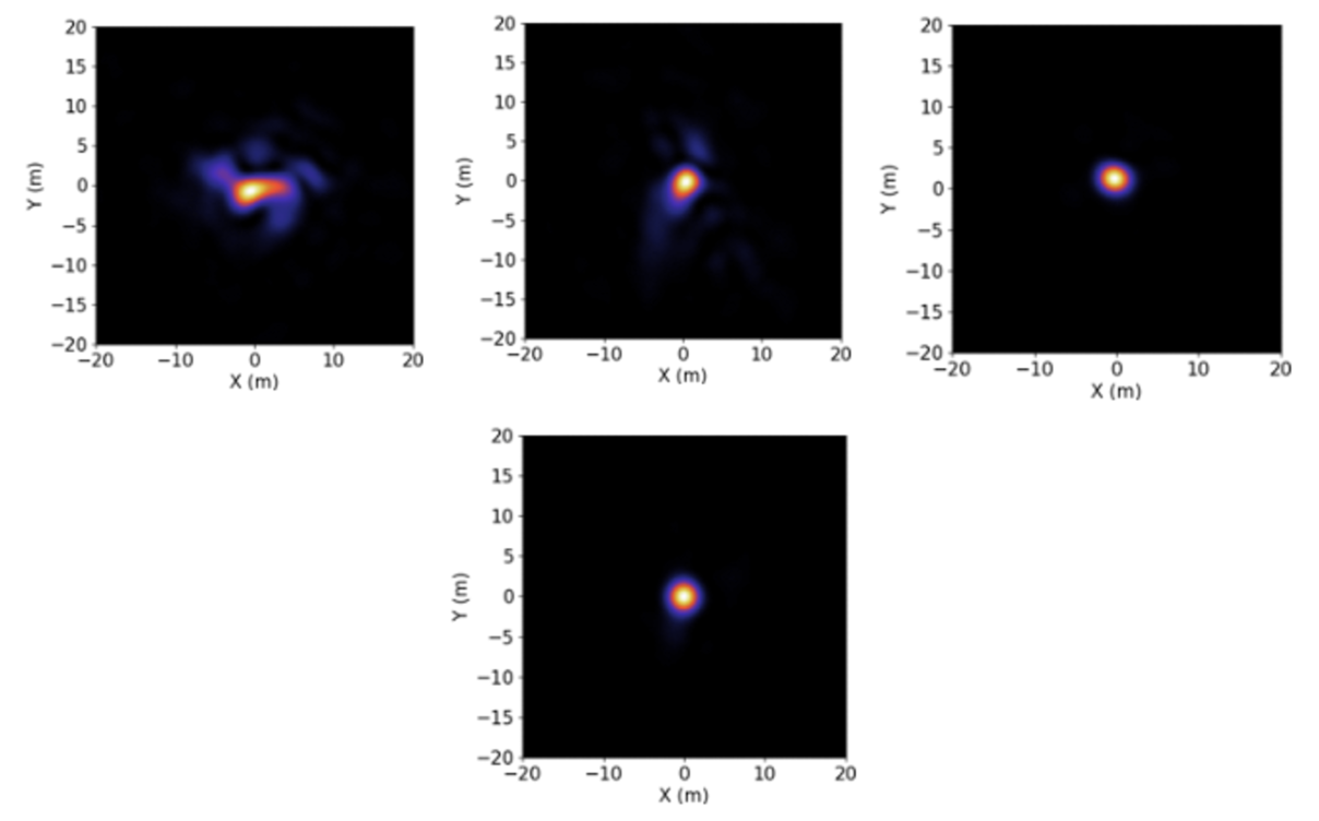
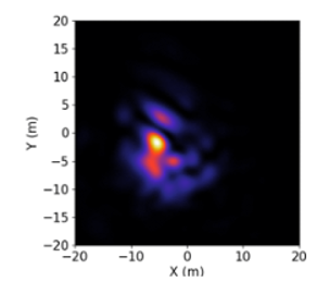
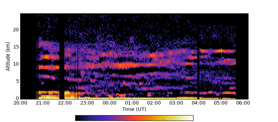
Atmospheric optical turbulence is detrimental to free-space optical communications. After propagating a laser through the atmosphere the beam appears to wander and breaks into speckles (Figure 1). The structure of this effect and the magnitude depends on the size of the transmitter, the size of the receiver and the distance from the turbulence. The Earth’s atmospheric is a dynamic environment and the turbulence structure can change rapidly. The refractive index variations that cause the beam distortion vary on time scales of milliseconds. Also, atmospheric turbulence is not uniform in altitude but is actually constrained to thin layers (Figure 2, Osborn 2018). There is always a strong layer near the ground due to interactions with the ground and more layers in the ‘free atmosphere’ at higher altitudes. The strength and altitude of these layers changes in time scales of minutes to hours.
Adaptive Optics (AO) can be used to correct for these distortions in real-time. AO requires a source of light to sample the atmosphere. In astronomy, this would be a star. In FSOC this could be a beacon on a satellite or a laser guide star – an artificial star created at the top of the Earth’s atmosphere in the mesosphere by exciting sodium atoms with 589nm light, these then re-emit creating a light source at 90km above the Earth’s Surface.
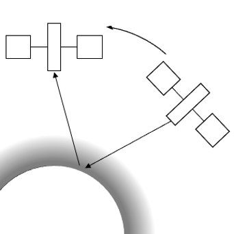
For downlink, the beacon on the satellite is sufficient to drive the AO system. However, for uplink, there is an additional complication, satellites move. To point a laser at the satellite we need to point the uplink laser ahead of where the satellite currently is, to where it will be when the light gets there (Figure 3). For LEO the point-ahead angle is approximately 10arcseonds (50microrad) and for GEO (which do still have a point-ahead angle due to rotation of the Earth and station keeping) approximately 4arcseconds (20microrad).
This point-ahead angle means that simply using a beacon from the satellite as the probe for the AO system results in residual error due to the difference in the atmospheric path between the uplink and the downlink. The magnitude of the residual error depends on the point-ahead angle. Smaller point-ahead angles (i.e. GEO) will have smaller residual error. The effect of the residual error (i.e. the distortion and hence fade at the satellite), depends on the design of the ground station (aperture size, AO configuration). Small launch apertures lead to a larger beam divergence due to diffraction of the beam, this makes them less sensitive to residual optical turbulence. Larger apertures lead to smaller beams at the plane of the satellite due to a smaller diffraction angle. This makes larger apertures more sensitive to atmospheric turbulence but they have the potential for a higher link flux if using AO. Figure 4 shows some example images with various types AO correction for a fictional 40cm ground station. See Osborn 2021 for more details.